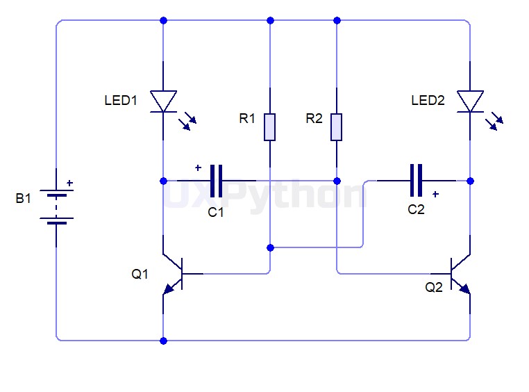
This is a circuit for the 3V dual LED flasher using PNP transistors. It uses two transistors to flash or blink two LEDs on and off alternately.
| Identifier | Component | Value | Count |
|---|---|---|---|
| R1, R2 | Resistor | 100K Ohm | 2 |
| C1, C2 | Electrolytic Capacitors | 22uF | 2 |
| Q1,Q2 | NPN Transistor | BC547 | 2 |
| LED1, LED2 | Light-emitting diode | 5mm LED (Any Color) | 2 |
| B1 | Battery | 3V | 1 |

When working this circuit, assume that the Q1 transistor runs first. Then LED1 connected to the Q1 transistor should grow more brightly. because, the current flows through LED1, and the collector to the emitter of the Q1 transistor. Also, some current will flow through LED2 and charge into the C2 capacitor until full using that current. Then, The voltage Base - Emitter (Vbe) is lower than 0.7V. So the Q1 transistor turns off, and LED1 goes out.
Then, the Q2 transistor starts working. LED2 connected to the Q2 transistor grows more brightly. The C1 capacitor charges until full. The voltage Base - Emitter (Vbe) of the Q2 transistor is lower than 0.7V. It turns off, LED2 goes out.
After that, the Q1 transistor will turn on and LED1 connected to the Q1 transistor will grow up again. the circuit will do this process continuously. Therefore, this circuit is called the Multivibrator.