The ASY13-1 is a bipolar junction transistor (BJT) with an PNP-type configuration. That means the ASY13-1 transistor has a negatively charged layer between two positively charged layers. This transistor has three terminals Base, Collector, and Emitter.
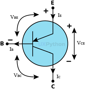
The ASY13-1 transistor symbol shows an arrow from the emitter into the base. This means that the current flows from emitter to collector terminal.
Circuit diagram symbol of the ASY13-1 transistor as follows.
| Transistor Code | ASY13-1 | |
|---|---|---|
| Transistor Type | BJT | |
| Transistor Polarity | PNP | |
| Transistor Material | Germanium(GE) | |
| Package | TO1 | |
| Collector Power Dissipation (Maximum) | PC | 0.15W |
| Collector-Base Voltage (Maximum) | VCB | 60V |
| Collector-Emitter Voltage (Maximum) | VCE | 60V |
| Collector Current (Maximum) | IC | 0.6A |
| Operating Junction Temperature (Maximum) | TJ | 75°C |
| Emitter-Base Voltage (Maximum) | VEB | 10V |
| Forward Current Transfer Ratio (hFE Value) | 20 | |
| Transition Frequency | FT | 0.8MHz |
UXPython is not the creator or an official representative of the ASY13-1 PNP transistor. You can download the official ASY13-1 PNP transistor datasheet to get more infromation about this transistor.
Note : Copyrighted materials belong to their creator or official representative.

Copyright © UXPython inc. All rights reserved.
Devoloped by UXPython.